Understanding an Electrical Symbol Chart
An electrical symbol chart may be useful in electrical engineering and other aspects of the professional electrical field. It is defined as a pictogram used to represent various electrical and electronic devices. They can be used in a schematic diagram of an electrical or electronic circuit. If you are in a line of work where these can be necessary applications, you may want to get familiar with it. Here are some basic electrical symbols and their meanings.
Basic Electrical Symbol Chart
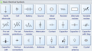
Here are some of the more basic electrical symbols you will find on a chart. See below for definitions.

Earth Electrode: A conductor of electricity partially buried in the earth that can provide a reliable conductive path to the ground. Can include a metal plate or water pipe.
Cell: Device containing electrodes immersed in an electrolyte. This is used for generating current of electrolysis.
Battery: Converts chemical energy to electricity, container consisting of one or more cells used as a source of power.
Source: Carries flow into an inter-electrode channel, part of a field-effect transistor.
Ideal Source: This refers to both ideal voltage source and ideal current source. An ideal source is a theoretical concept of an electric current or voltage supply that has no losses and supplies perfect voltage or current supply.
Resistor: Device that has resistance to passing electric current.
Capacitor: Device used to store electric charge. A capacitor will consist of one or more pairs of conductors separated by an insulator.
Antenna: Electrical device that converts electrical power to radio waves and vice versa.
Basic Electrical Symbol Chart: Switches and Relays
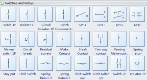
This next image will provide an electrical symbol chart showing commonly use switches symbols. Some definitions are below.

Switch: Makes and breaks a connection in an electric circuit.
Isolator: Mechanical switch that isolates one part of the circuit from the system as needed for safety purposes.
SPST: a single pole single throw switch
SPDT: a single pole double throw switch
DPST: a double pole, single throw switch
DPDT: a double pole, double throw switch
Basic Electrical Symbol Chart: Transmission Path Symbols
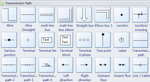
This image provides an electrical symbol chart for devices used for transmission of electricity. Definitions are below.

Wire: Connects the components in a circuit.
Test Point: A location in an electrical circuit used to monitor the state of circuitry or inject test signals.
Outward flow: Recognized current flowing outwardly as opposed to inward flow with flows inwardly.
For a very basic example of how these symbols might be used in an actual application, see below for an illustration of a basic circuit:

We can see how the switch, battery, resistor and LED light are all comprised in making up an electrical circuit. In more advanced electrical symbol use, labeling is not likely to be present.
While understanding an electrical symbol chart can be a pretty advanced skill in the electrical field, it may come in handy in everyday life as well. You never know when one of these symbols might pop up!
